JvSIM components
About
The JvSIM components is a set of simulation components including TJvSimLogicBox for "no code" simulation of digital electronics and TjanSimPID and TjanSimScope for analog instrumentation simulation.
Author
The original author is Jan Verhoeven who donated his Delphi components to the Jedi Project.
Download
The components belong to JVCL components of the Jedi project. A Lazarus port can be downloaded from Lazarus CCR at source forge.
Packages and Installation
The JvSIM components consist of the packages
- JvJansLazR.lpk (runtime package)
- JvJansLazD.lpk (designtime package).
They depend on the general-purpose JVCL packages
- JvCoreLazR.lpk (runtime package)
- JvCoreLazD.lpk (designtime package)
For installation
- compile JvCoreLazR.lpk, JvCoreLazD.lpk, JvJansLazR.lpk, JvJansLazD.lpk
- install JvJansLazD.lpk
The installed components appear on the tab JVCL of the component palette.
Digital simulation
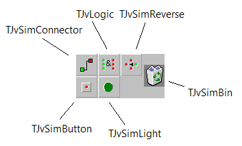
The JvSim components can be used for educational purposes to demonstrate boolean operations without writing any code. The basic work horse is TJvSimLogicBox. It acts like a pre-built toolbar from which the other components can be dropped on a window at runtime.
The icons of the subcomponents refer to
- TJvLogic - a logical connection unit providing AND, OR, NOT, NAND, NOR, and XOR operations. The functions can be toggled by clicking into the central, button-like part of the component. Its input terminals are identified by green, output terminals by red circles. They also act as LEDs and indicate whether a logical "1" (bright) or "0" (dark) is present.
- TJvSimConnector - a simple connecting wire. The ends of the wire have red and green terminals. As a basic rule of the JsSim components, red can only be connected to red, and green only to green.
- TJvSimButton - a digital input source displayed like a button. When the button is pressed a logical "1" is generated, otherwise the signal is "0". The button can be toggled between both states by clicking on the central button-area. An LED in the middle indicates whether the signal is "1" (bright) or "0" (dark). The fact that the color of the LED is red symbolizes that the button is an output source.
- TJvSimLight - displays a logical signal like a light bulb or LED. When the LED is lit a logical "1" is applied to the component. When it is OFF a logical "0" is applied. The element acts like an input terminal, i.e. it must be connected to the green end of a TJvSimConnector.
- TJvSimReverse - I'm not sure about this one - it could be a wiring tool helping to wire elements back to the left side of the logical circuit. It has one input and three output terminals and just passes the input signal directly to the outputs.
Let's play with the component and demonstrate the logical OR operation.
- Add a TJvSimLogicBox near the top left corner of an empty form
- Compile and run the program.
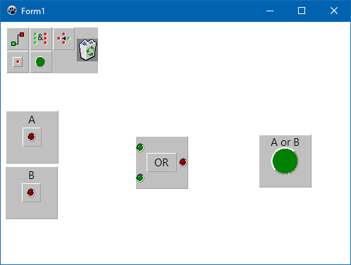
- Click on the TJvSimButton icon to drop an input data source. The button appears below the logic box; drag it away from this place because this is where all the other components will appear. Move it a bit deeper, but keep it at the left side of the form -- this is because the "circuit" will be read from left to right. The center part of the element is a button. If you click on it you can turn the signal on and off, the LED in the center indicates the signal. If you double-click on the area above or below the center button you can open an input box in which you can enter a label for the element. Give it the name "A".
- Add another TJvSimButton. Move it below button "A". Set its caption to be "B".
- Add a TJvLogic element. Drag it to the center of the form. In the middle of the element, the currently selected logical function is displayed (AND by default). Click on the this button to iterate through all functions available. OR appears after the first click. If you missed it, clicked several times until the OR comes back.
- Add a TJvSimLight element. Drag it to the right of the form. By default it resembles a green LED. If you want to change the color double-click on the round LED and pick the new color from the dialog.
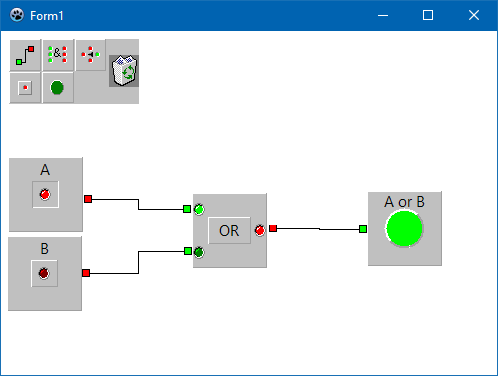
- What is missing is the wiring of the elements. Add a TJvSimConnector. It is an angled wire with a red and green terminal. Double-click on one of the terminals if you want to change the shape of the wire (straight, 1 or 2 kinks). Drag the red terminal near the border of the first input source, drag the green termin near the upper green terminal of the TJvLogic element.
- Add another TJvSimConnector. Drag its red terminal to the other input source, and its green terminal to the other green input terminal of the logic element.
- And finally a last TJvSimConnector. Drag the red terminal to the red output of the logic block and the green terminal near the border of the LED indicator. Note that the color of the TJvLight is for decorative purposes only; even if switched to red the element is still an input device and requires a green wiring terminal.
- Done.
- Click on button "A". The button's red LED, the green input LED and red output LED of the logic block, as well as the indicator LED are switched on. All these terminals have a logical "1". The other input LED of the logic block is dark, it has a "0". Our experiment indicates that the logical OR of A=1 and B=0 is 1.
- Change the input parameters. You will notice that the output LED is always ON, except for the case that both input signals are OFF. This is exactly the behavior of the OR function.
- Switch the function of the logic block to AND and demonstrate that the result of AND is "1" only if both input signals are "1".


